Architecture
Conditional Logic
Semiconductors
Instruction Set
Serial Console
Example Programs
Build/Dev Log
Comments
Development LogExperimentsAfter thinking about building a relay-computer for a while, I started focusing on the flip-flop design and came up with idea for a master-slave flip-flop with a capacitor-based latch for the master side and a hold resistor based latch for the slave side. Of course I wanted to try it, so I designed a 4-bit counter: 
And tried it on a bread-board: The above video is a re-creation: at first I thought it would be better to use 24V relays, since I thought they would have better fan-out. Eventualy I realized that the cost of a 24V power supply would have been a big problem, so I switched to 12V. None the less, I bought a bunch of 24V relays which I used for these experiments. A relay PDP-8 ?I thought it would be neat to make a relay-based clone of a real computer, and of course I needed a really small one so naturally I focused on a PDP-8 minicomputer from DEC. So I designed one. I wrote a Verilog version of the PDP-8 to pre-verify the design and help with optimization. Here is the Verilog PDP-8.I designed the PDP-8 in schematics using 227 24V relays. I also did a gate level simulation of this design, so I'm fairly confident it will work. Here is the relay PDP-8 schematics.Trainer...But with more thought, I've decided the PDP-8 is little silly. It would be so slow that running any real software wouldn't be very interesting. Also, I ended up being more interested in making something I could mass produce and possibly sell. 227 relays is just too big and too expensive for such a toy. Still, I've given the design above and perhaps someone would like to build one. So I came up with a list of constraints for a more reasonable relay-based computer:
Anyway, I toyed around with modifications to the PDP-8 design. Perhaps I could keep all the same concepts but make an 8-bit version? I finally hit upon a number of changes which reduced the design:
Front PanelI was originally planning on having LEDs and switches for the front panel. However, it turns out that switches are quite expensive- in fact more than the 7-segment LED-display and keypad that I now have. Also I knew from experience that although switches have a nice nostalgia value, they are in fact very tedious to use. DesignI use older design tools that I bought when I was working as a consultant in the mid 1990s: DOS OrCAD SDT 386+ for schematic capture and PADS PowerPCB version 3.5.1 for PCB layout. I have access to newer tools at work (Allegro, ConceptHDL), but they are certainly not mine to use for home projects. I should probably learn an open source tool like gEDA, but I already know the tools I own. OrCADI've used DOS OrCAD for many designs including PCB designs and Xilinx FPGA designs using Xilinx XACT (now I use Verilog for FPGAs, and would have used it even then if it was available) and has one of the best user interfaces of any software tool. With some recent video drivers DOS OrCAD now works better in Windows-XP than it ever did in MS-DOS. Tragically, 64-bit versions of Windows do not support VM86 mode, so OrCAD doesn't run well (you could use DoSBOX, but it's not as good). Long mode does not directly support Virtual 8086 mode, but with work Microsoft could have pulled it off (switch to 32-bit Protected mode, then switch to VM86 mode): see v86-64 for Linux. 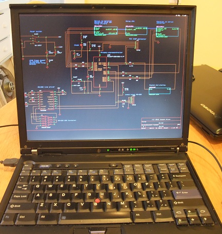
I wrote a tool to convert OrCAD to Verilog so that I could run a "gate-level" simulation of the design (look for the Verilog netlister in the files section of the OldDosOrCAD Yahoo group) using the open source Icarus Verilog and GTKWave. This influenced the design style I used. Basically it's a very hierarchical design, where the relays only appear in the leaf pages, and the leaf pages are simple and small. Each leaf page is replaced with a Verilog model whose source is written as a comment embedded on the schematic page itself. This simulation was more important when I was going to make a relay clone of the PDP-8, since I definitely wanted to simulate the complex control logic. The Trainer design is simpler, so I never did the gate level simulation. I also have OrCAD Capture 7.2 (I got it when I was still paying maintenance) which can import SDT 386+. I used this to generate the .pdf version of the schematics. I tediously annotated the schematics with Acrobat so that you can traverse the hierarchy by clicking on blocks. Supposedly there is a script to do this in much more recent version of OrCAD Capture, but it does not work in the free versions and I'm not buying it. PADSI own and have used PADS for DOS, but PowerPCB is better (I prefer it over Cadance Allegro). I have the Specctra autorouter and the PADS Blaze autorouter (PADS gave Blaze to customers on maintenance for free when it was first developed). I used the Blaze autorouter for the Relay Trainer: it takes Blaze less than a minute on my old IBM T41 laptop to route the entire design. All the real work is in the placement, footprint creation and silkscreen design. 
One huge annoyance with PowerPCB is that it uses a parallel port dongle for licensing. I'm stuck needing a machine with a real parallel port for this. My IBM T41 is dying (it has the cracked video chip solder ball problem), so I'm soon going to have to buy another one to keep a working CAD station. Until it dies completely I've found I can make progress by bending the entire laptop slightly. 
First buildFor the first build, I had PCBs made, but purchased and assembled the components into the board myself. I bought 10 boards, but assembled only one of them. For high-end (high speed, many-layer) designs, I've always used Sierra Proto Express (I always thought it was cool that I could send them an 8-layer board design by 9 PM on the east coast, and have the fabricated boards back by the next morning). For this low-tech two-layer design I only care about cost, so I was willing to try other places and wait a week for the fab time. I ended up using Advanced Circuits- they are popular and a bit lower cost than Sierra Proto Express. The raw boards from Advanced Circuits were quite nice:
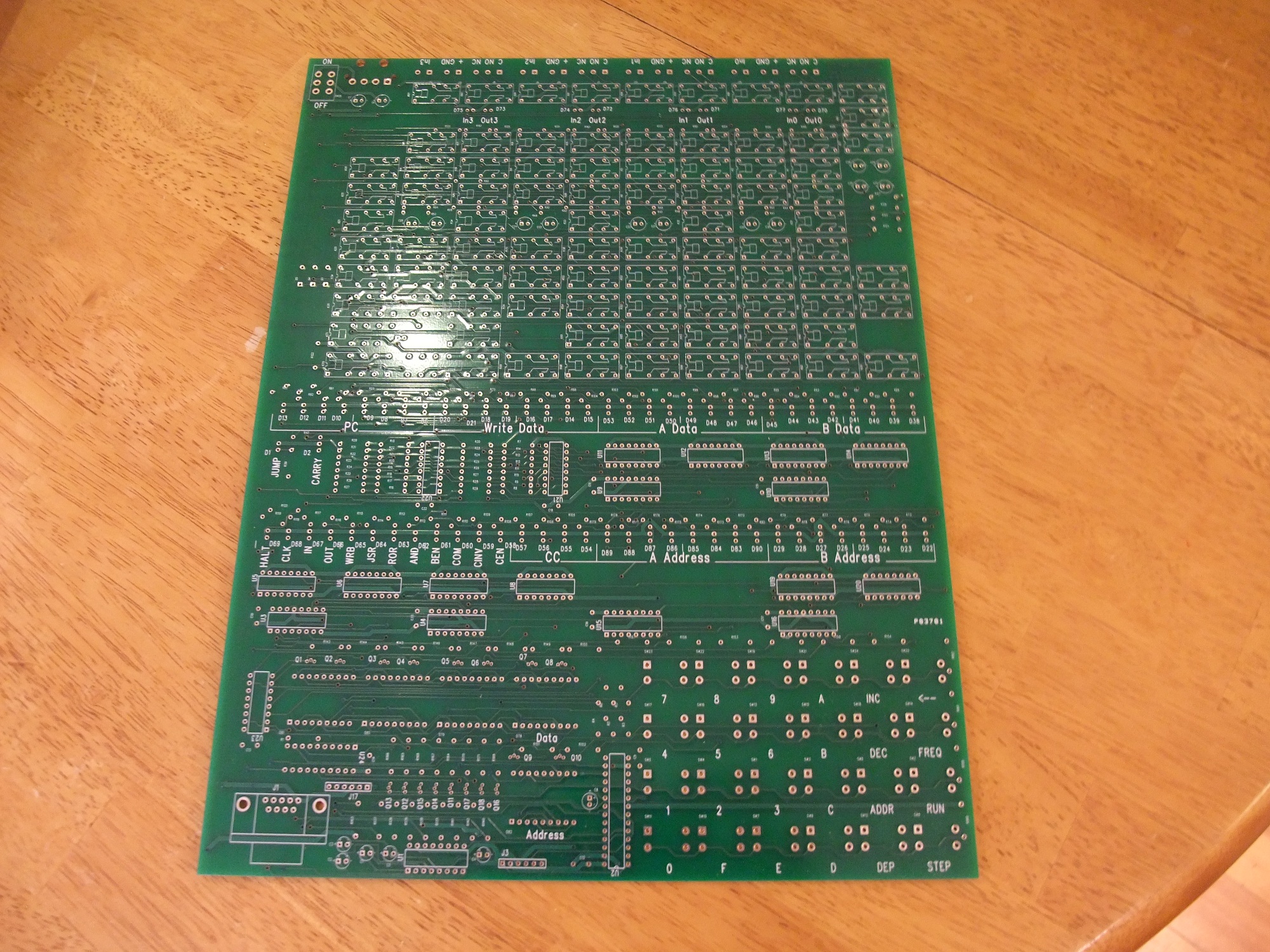 Click for high resolution This is what it looks like assembled: 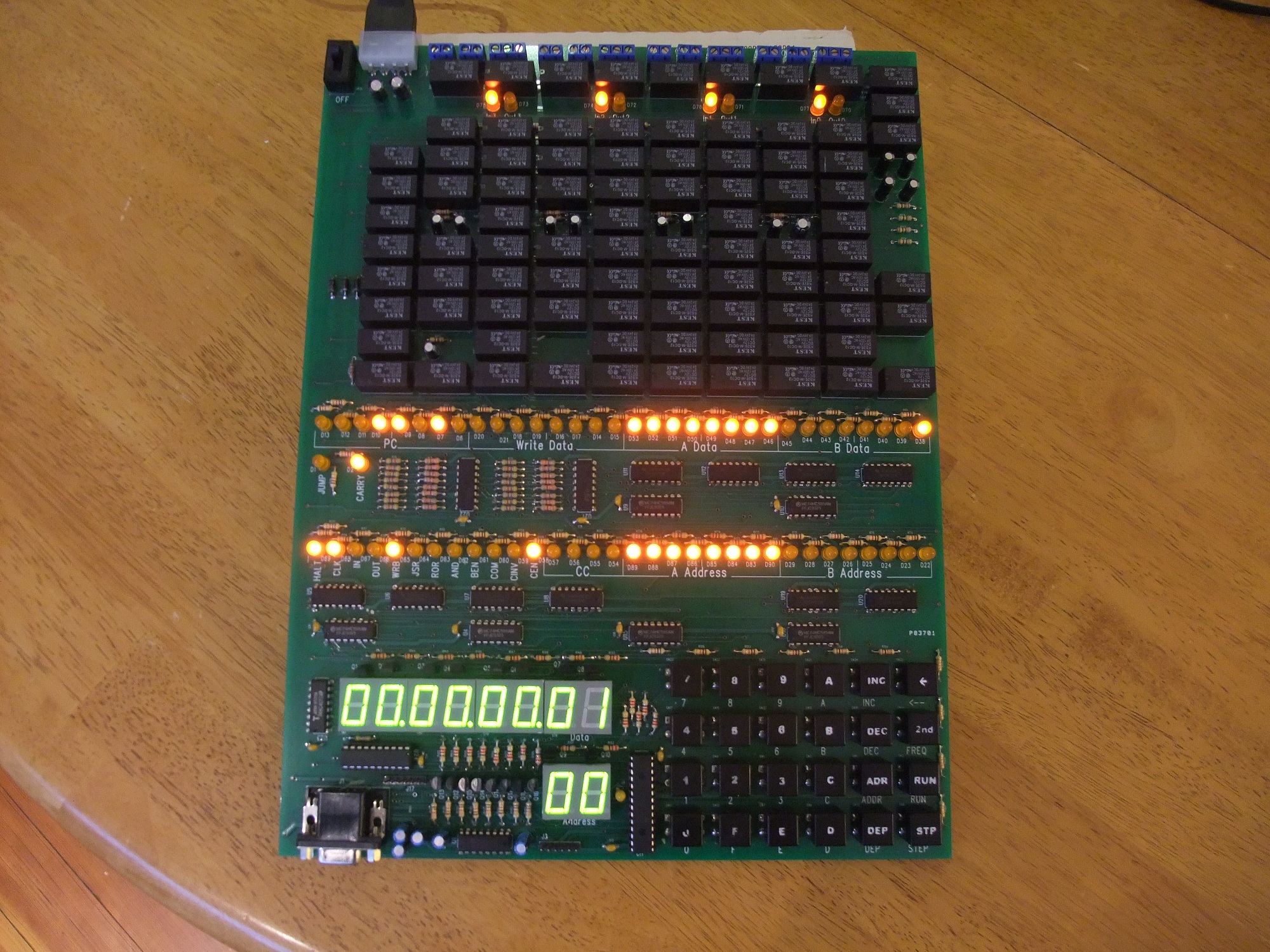 Click for high resolution Unfortunately I made a horrible mistake in the schematic symbol for the relays: I had reversed the pin numbers between the normally open and normally closed pins! I remember reviewing the symbol, thinking it was wrong, and "correcting" it. What a massive screw-up: I'm usually pretty good with this kind of detail, but this time my luck definitely ran out. So then I had to decide, make another run of boards or fix each relay by hand with cuts and jumpers to each relay? Well I wanted to debug everything before spending more money, so I did the latter. This is what it looks like:  Click for high resolution There were a few other minor mistakes, so even if the symbol was not messed up the board would not have been perfect. Still, a few jumpers would have been fine with me but the symbol mistake made it impossible. Even with all these cuts and jumpers the board did finally work. ButtonsNotice that the "tactile switch" caps have printed lettering on them. I experimented with screen-printing this lettering onto the caps and was planning on doing this in the final version. Here is the screen I made for this, from a Speedball kit from the local art store. 
This ink worked for the smooth plastic caps: 
Even so this screen printing is a lot of work, so I looked for alternative solutions. One idea was to get die-cut lexan stickers for the buttons, but for sure there would have been an NRE charge and there is still work to put the stickers on the buttons. As it turned out these large button caps were not available for the second build and the smaller caps reveal enough of the PCB screen printing so that no lettering is needed. Second buildFor the second build I wanted to try to get the boards assembled by a contract manufacturer. At first I was discouraged because most places that are willing to do small runs are really set up only for surface mount technology. They will do through-hole parts, but they don't have any automation for it so they charge a lot for manual insertions. I was seriously thinking of changing to all surface mount, though I thought through hole would be a better option for kits. Surface mount is great for most parts, but not relays, cheap LEDs, switches or connectors. Surface mount relays do exist, but they are quite a bit more expensive than the through-hole versions. Of course it's possible to have a mixed surface mount and through-hole board, but this also costs extra since it means having both reflow and wave-soldering steps. MyRO PCBI finally chanced upon MyRO PCB. They have a sales office in Canada, but their factory is in China. They have such reasonable prices for through-hole assembly that I gave up on the idea of switching anything to surface mount. I don't know if they have through-hole insertion machines, or if the low price is entirely due to the labor costs; perhaps it's both. Anyway, I gave them a try. Part orderingMyRO will purchase parts for you if you give them a BOM (Bill of Materials), for a fee. They can purchase from the big distributors like Mouser and Digikey, and want you to use these distributors' part numbers. They do not deal with some smaller companies such as Jameco, or directly with component manufacturers- well at least they would not buy relays from a Chinese relay manufacturer. They will also accept parts shipped to them. I ended up having them buy everything except for the relays, which I bought direct from Kest. This did not work out as well as I had hoped because shipping to China is expensive. It's well worth MyRO's fee to have them buy the parts for you. Anyway, I gave them the design, the BOM and money, and three weeks later 10 assembled boards arrived at my home. Here is a list of the changes to the design between the first and second builds:
This time, the boards had no wiring mistakes but there were still problems. Relay TroubleFor the first build I bought 12V DPDT DIP "Kest"-branded relays from All Electronics. They worked fine, so I figured I'd be conservative and use the same part for the second build. MyRO will not buy from All Electronics, so I figured I'd save money by buying 830 relays directly from Kest, who turn out to be in New Jersey. These relays seem to be different from the ones from All Electronics, even though they have the same part number. First of all the case is orange instead of black, but I sure wish that was the only difference. The orange relays seem to have weaker springs, so that even though the coil resistance is the same as the black ones, the needed holding current is much less. It means that the relay-based flip-flops will turn on, but will not turn off again. I had to increase the value of the holding resistors for sure. But just increasing the holding resistors didn't work. Some of the relays wouldn't stay on and need smaller holding resistors. There is a wide enough variance in the relay spring strength that I ended having to tune each relay! So much for a turn-key build process. To tune the holding resistors I replace the original 1.8K holding resistors with 4.7K, and then solder either a 10K or a 6.8K resistor in parallel on the back of the board for the ones which need more current (I could just replace the resistors, but each time you de-solder a resistor it damages the board to some degree, so it's better to add them). 
(The two jumpers shown are for fixing traces I broke during debugging and are not needed on "fresh" boards). Here is a table of measurements for five of these orange Kest KS2E-M-DC relays:
Min is the minimum value of the hold resistor below which the relay is stuck on. Max is the maximum value of the hold resistor above which the relay won't stay on. The largest min is 3.26K and the smallest max is 3.56K so the mean is 3.41K and the window is only .3 K! Here is a table of a sampling of five new TE Connectivity / Axicom MT2 C93418 relays I'm considering using instead for the next build:
The largest min is 1.04K and the smallest max is 2.38K, so the mean is 1.71K and the window is 1.34K, which is much more reasonable. These relays are closer to the black Kest KS2E-M-DC12s, where I got the original 1.8K value for the hold resistor. You could argue that I'm not using the relays in their intended way by using the holding resistors. Still, I'm surprised at the huge variance. Unfortunately the problems do not end there: about 2% of the relays are just plain broken. The coil is OK, and I can hear them click, but the contacts do not close. Incidentally here is a simple jig to test my relay flip flops: 
This is a single bit flip-flop counter with the D input driven by an SN754410 half H-bridge driver. This chip has to be in the circuit because its low level output voltage is about 1V, not ground like the relay flip-flop outputs. I also use this jig to determine the capacitor value the input resistor value and the maximum frequency. For the next build, I intend to use a different brand of relay, perhaps the one above. I've found that there are two commonly specified drop-out voltages: .6 V and 1.2 V. I suspect that the 1.2 V ones will work better. I've also spent more time in Mouser's on-line catalogue and found some lower cost relays. Searching for parts on Mouser is definitely a skill all on its own since they have so many parts that it is easy to miss ones, and the lowest cost options are not always prominently displayed. NoiseI found that the load and clock lines of the 74HC595 chains were picking up noise on the second build. I did not have this issue on the first build, but the routing is different and the brand of 74HC595 is different. Anyway, the fix was to add capacitors to these signals- you can see them on the back of the board in the photo above. |