Architecture
Conditional Logic
Semiconductors
Instruction Set
Serial Console
Example Programs
Build/Dev Log
Comments
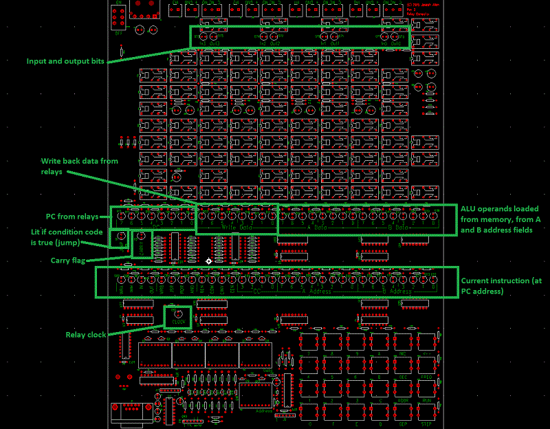
Relay Computer Quick Usage GuideLEDsThis diagram shows the discrete LEDs:  DisplayThe 8-digit data display shows to contents of the memory address shown on the 2-digit address display. If the upper 16-bits of memory contains a halt instruction (wra and wrb bits both set), then it's assumed that the memory address is being used for a data byte, so only the lower byte and the lower bytes of the next three addresses are shown. Decimal points are illuminated in this mode: 00.00.00.00 Showing data bytes of four addresses If memory contains any other instruction, then the full 32-bit instruction is shown. Decimal points are off in this mode: 00 00 00 00 Showing instruction in a single addressData / Address entryType 2 - 8 hex digits. Use ← key for backspace. Backspace all digits to cancel data entry mode. Save / Restore memory to non-volatile storage2nd DEC Restore memory from non-volatile 2nd INC Save memory to non-volatile (Only lower 128 addressess are saved/restored). Modify display address<address> ADR Set Address INC Increment address DEC Decrement address Write data to memory<data> DEP Write data (deposit) to current address <data> INC Write data to current address and increment address <data> DEC Write data to current address and decrement address Change operating frequency2nd 0 Speed controlled by knob 2nd 1 Slowest ... 2nd F Fastest The default speed is 5 Program execution<address> STP Set current Program Counter STP Single Step <address> RUN Set Program Counter and run RUN Run until halt instruction or STP key pressed Input and output bitsThere are four output bits implemented as relay flip-flops. Each of these bits is available externally as relay contacts. Both the normally open and normally closed contacts are wired to the connectors. 12V and ground are wired to external connectors also. These may be used along with the output relay contacts to control small lamps. There are four input bits wired to connectors. It is expected that switch closures are connected to these. When a switch is closed, the input registers a '1'. When a switch is open, the input registers a '0'. If I/O is not needed, the outputs may be connected to the inputs to produce an extra programmable register implemented with relay flip-flops. |